PATENT SPECIFICATION (BRITAIN)
415,280
Convention Date (Austria): Nov. 2, 1932.
Application Date (In United Kingdom): Oct. 31, 1933. No. 30,236/33.
Complete Accepted: Aug. 23, 1934.
COMPLETE SPECIFICATION.
Improvements in or relating to Water Conduits.
I, VIKTOR SCHAUBERGER, an Austrian citizen of I. Renngasse 6, Vienna, Austria, do hereby declare the nature of this invention, and in what manner the same is to be performed, to be particularly described and ascertained in and by
The following statement: -
This invention relates to means for improving the flow of water or the like in pipes, channels and other conduits, made of such materials as conduits are normally made of, for example, cast metal, sheet metal, wood, earthenware, and so forth.
It is already known to improve the flow of water in pipes and channels by providing them with guide-blades which project from the wall towards the centre, the faces of the blades being curved in such manner as to force the water from the wall towards the middle of the water-conduit, to which end the blades are in the form of a plurality of helices, similar to multiple thread rifling. Further it has been proposed heretofore to provide the faces of guide-blades with grooves running spirally in the direction of flow of the water.
The object of this invention is to provide an improved construction or arrangement of guide-blades whereby the forward motion of the water in the core zone is favoured in comparison with the flow of water in the region of the walls. Simply stopping the flow of the wall zone would cause turbulence in the region between the core and wall zones, and the production of a sufficiently well formed core zone would be unfavourably influenced.
In the case of this invention however, the wall zone of the water is divided up into separate whirl formations which are of such a structure as to possess sufficient interior stability to have little tendency to break up, and therefore as a whole to produce a sheath of water favourable to the progress of the core water.
In accordance with the foregoing, according to the present invention, guide-blades are employed which are twisted in the manner of turnings in such manner that two co-operating guiding members having screw-like surfaces are formed, one of which separates the wall zone of the water current from the core zone whilst the subsequent guiding member in the direction of flow imparts a rotary motion to the separated wall zone of the water, whereby the wall zone of water is divided up into separate stable whirls. The invention is preferably applied to guide-blades which are disposed in the conduit along multiple spiral lines, producing a multiple rifling effect, so that the wall zone of the water progresses with a generally spiral motion.
In carrying the invention into practice the guide blades may be in the form of substantially rhomboidal strips, the diagonally opposite obtuse angled corners of which are bent up towards the same surface of the blade.
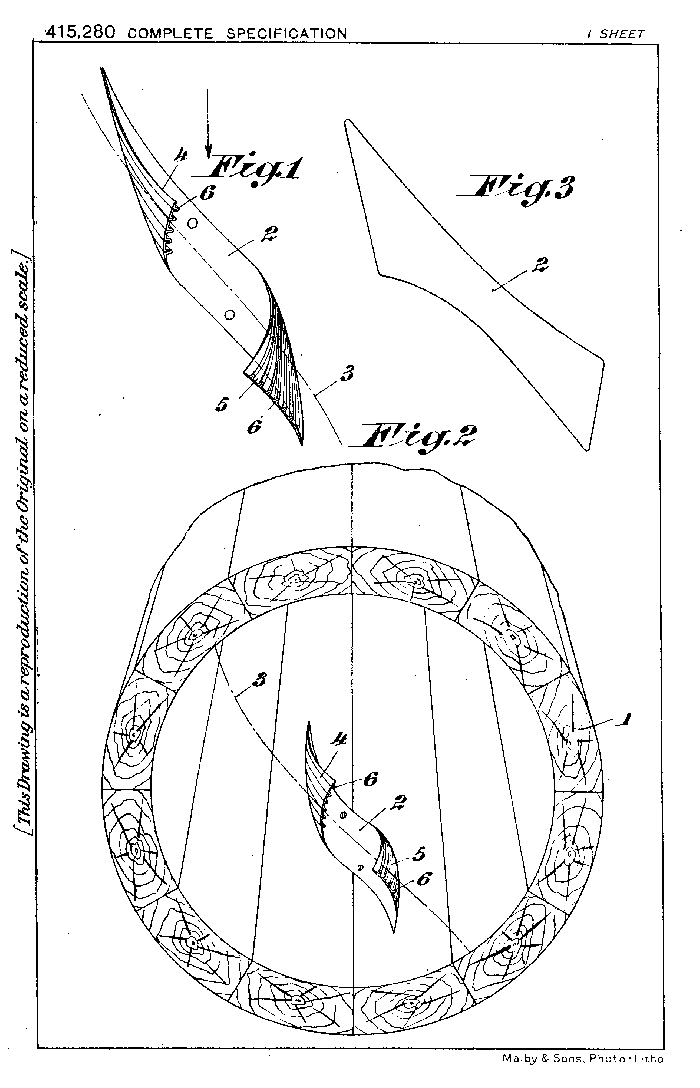
The invention is illustrated by way of example in the accompanying sheet of drawings in which Figure 1 is a plan view of a guide blade, and Figure 2 shows a pipe section with a guide blade therein, viewed against the direction of flow. Figure 3 shows the developed surface of a guide blade.
The guide blades are twisted in the manner of turnings, so that two guide members are formed, one at each end, as shown in Figure 1. These two guide members impart a spiral motion to the wall zone of water which flows generally in the spiral direction 3, thus producing a spiral sub-motion of the wall zone within its general spiral movement.
The guide blades 2 are preferably, as shown, disposed in the pipe 1 along multiple spiral lines 3, it being understood that, for the sake of clearness, one blade only is shown in the drawings. The guide member 4 of the blade 2 serves to impart a spiral flow directed away from the centre of the conduit, so that the wall zone becomes separated from the core zone of the water, whilst on leaving the part 5 of the blade, a spiral movement directed towards the middle of the conduit is imparted to the wall zone of the water stream The action of the strips 2 is improved by ribs 6 provided on the surfaces of the strips 2 as shown in the drawings, and the ribs may be thicker at the roots than at the tips so that the intermediate grooves narrow towards the surface proper of the strip 2.
Instead of being formed from a common strip 2, the guide members 4 and 5 may be made separately from each other. The guide blades may be made of metal, wood, clay, earthenware, or of any other suitable stiff material.
Having now particularly described, and ascertained the nature of my said invention and in what manner the same is to be performed, I declare that what I claim is: -
1. Water conduits having blade like elements projecting from the wall towards the central portion of the conduit, and providing guiding surfaces for the water, wherein the guide blades are twisted like turnings, so as to produce two co-operating blade like members having screw like guiding surfaces, one of the said members separating the wall zone of the water current from the core-zone, whilst the subsequent member in the direction of flow imparts a rotary motion to the separated wall zone of the water, whereby the wall zone of water is divided up into separate stable whirls.
2. Water conduit according to claim 1, wherein the guide blades are disposed in the conduit along multiple spiral lines, producing a multiple rifling effect, so that the wall zone of the water progresses with a general spiral motion.
3. Water conduit according to claim 1, in which the guide-blades are in the shape of substantially rhomboidal shaped strips, the diagonally opposite obtuse angled corners of which are bent up towards the same surface of the blade.
Dated this 31st day of October, 1932.
CHARLES S. PARSONS,
Chartered Patent Agent,
Thanet House, 231, Strand, London, W.C. 2.
Redhill: Printed for His Majesty's Stationery Office, by Love & Malcomson, Ltd.-1934.
Return to Electrokinetic UFO page