The objective of this report is to reconstruct the experimental work carried out between 1946 and 1956 by John R. R. Searl that concerns the geometry, materials used, and the manufacturing process of the Searl-Effect Generator (SEG).
The information given here is based on private communication between the author (S. Gunnar Sandberg) and Searl and should be considered preliminary as further research and development may give reason to alter and/or update the content.
The SEG consists of a basic drive unit called the Gyro-Cell (GC) and, depending on the application, is either fitted with coils for generation of electricity or with a shaft for transfer of mechanical power. The GC can also be used as a high voltage source. Another and important quality of the GC is its ability to levitate.
The GC can be considered as an electric motor entirely consisting of permanent magnets in the shape of cylindrical bars and annular rings.
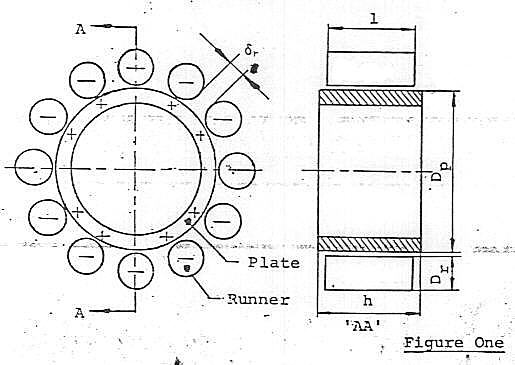
Fig. 1 shows the basic GC in its simplest form, consisting of one stationary annular ring-shaped magnet called the plate, and a number of moving cylinder-shaped rods called runners.
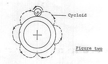
During operation each runner is spinning about its axis and is simultaneously orbiting the plate in such a manner that a fixed point p on the curved runner surface traces out a whole number of cycloids during one revolution round the plate, as shown by the dotted lines in fig. 2.
Measurements have revealed that an electric potential difference is prodeced in the radial direction between plate and runners; the plate being positively charged and the runners negatively charged, as shown in fig. 1.
In principle, no mechanical constraints are needed to keep the GC together since the runners are electromagnetically coupled to the plate. However, used as a torque producing device, shaft and casing must be fitted to transfer the power produced. Furthermore, in applications where the generator is mounted inside a framework, the runners should be made shorter than the height of the plate to prevent the runners from catching the frame or other parts.
When in operation, gaps are created by electromagnetic interaction and centrifugal forces preventing mechanical and galvanic contact between plate and runners and thereby reducing the friction to negligible values.
The experiments showed that the power output increases as the number of runners increase and to achieve smooth and even operation the ratio between external plate diameter Dp and runner diameter Dr should be a positive integer greater than or equal to 12. Thus
The experiments also indicated that the gaps δr between adjacent runners should be one runner diameter Dr as shown in fig. 1.
More complex Gyro-Cells can be formed by adding further plates and runners to the basic unit. Fig. 3 illustrates a 3-plate GC consisting of three sections, A, B and C. Each section consists of one plate with corresponding runners.
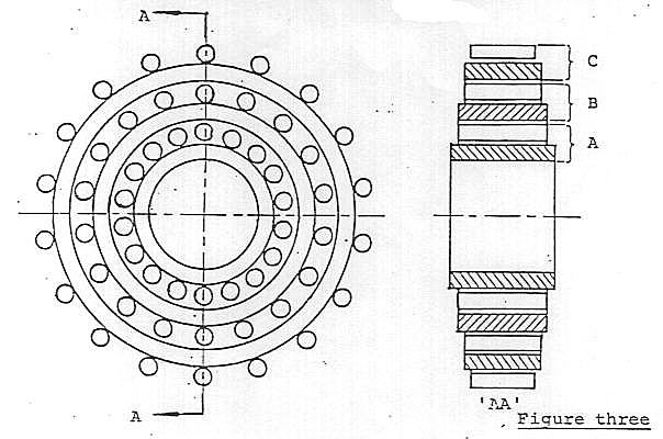
The experiments showed that for stable and smooth operation all sections should be of ecrual weight. Thus
WA = WB = WC
where
    WA = weight of section A,
    WB = weight of section B,
and WC = weight of section C.Due to a combined DC and AC magnetising process, each magnet acquires a specific magnetic pole pattern recorded on two tracks consisting of a number of individual north-poles and south-poles, as illustrated in fig. 4.
Magnetic measurements have revealed that the poles are approximately one millimetre across and evenly spaced. It was also found that the pole density δ - defined as the total number of poles N per track divided by the circumference, πD - must be a constant factor specific for a particular generator. Thus
where Np is the total number of poles per track on plate and Nr is the total number of poles per track on runner.
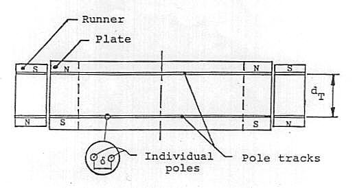
Furthermore, the distance dT between the two pole tracks must be the same for all runners and plates which are parts of the same GC.
The pole tracks allow automatic commutation to take place and create a tuning moment. Exactly how this is achieved is not understood and will require further research efforts. Likewise, the source of energy is at present unknown. Further research is also needed to establish the exact mathematical relationship between output power, speed, geometry and material parameters, such as mass density and electromagnetic properties of the materials used.
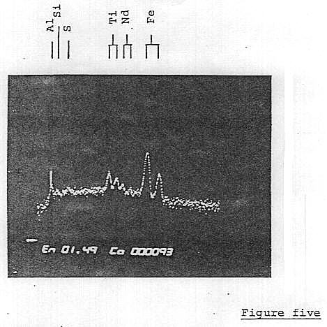
The magnets used in the original experiments were made of a mixture of two types of ferromagnetic powders imported from the USA. One of these magnets, still in existence, has been qualitatively analysed and was found to contain the following elements :
1. Aluminium (Al)
2. Silicon (Si)
3. Sulfur (S)
4. Titanium (Ti)
5. Neodymium (Nd)
6. Iron (Fe).
The spectrogram is illustrated in fig. 5.
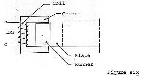
If the SEG is used as an electric power plant a number of induction coils must be fitted to the GC. The coils consist of C-shaped cores made of soft steel (Swedish steel) or high μ-ferrite (mu-metal). The number of turns and wire gauge used depends on the application. Fig. 6 shows the basic design.
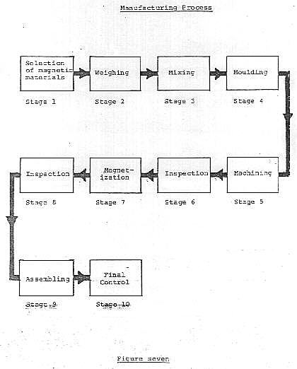
The block diagram in fig. 7 illustrates the main stages in the manufacturing process.
Stage 1 Magnetic materials and bonding agents
It is feasible that future research will reveal other magnetic raw materials to be cheaper and/or more efficient than the ones used in the original experilnents. It is also possible that other types of binder may improve the performance.Stage 2 Weighing
In general, to produce efficient magnets the right amount of each element contained in the ferromagnetic powder is crucial. It is therefore reasonable to suggest that when mixing different types of powders an optimal weight ratio does exist that will produce a 'best' magnet.Stage 3 MixingAt present, however, this weight ratio is not known for the powders used by Searl in his past experiments.Together with new magnetic materials and optimisation of generator geometry, this is an area in which research efforts could be profitable.
In general, the amout of binder used should be as small as possible to achieve maximum mass density of bonded magnets. However, the possibility that the binder is taking an active part in the generation of the Searl-Effect must not be excluded. For instance, the dielectric properties of the binder may play an active role in the electromagnetic interactions taking place in the SEG. If that is the case, then a further amout of bonding material may be beneficial.
The mixing is an important process which will decide the homogeneity and reliability of the finished product. A homogeneous mixture can be achieved by using turbulent air flow inside the mixing container.Stage 4 MouldingThe experiments did show that an improved performance was achieved if all magnets for the same generator were made from the same batch.
During the moulding process the compound - consisting of ferromagnetic powders and thermoplastic binder - is compressed and simultaneously cured by heating. Fig.8 illustrates the tool used for making 'blinds'. A 'blind' is an unmagnetized runner or plate/part of plate. When manufacturing large plates (Dp > 30 cm) it may be necessary to make them in segments rather than in one piece.
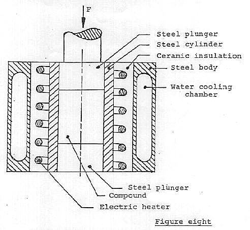
The figures given below should be considered as guide lines only, since correct data are not available regarding the influence of the moulding process on the Searl-Effect.Stage 5 Machining1. Pressure: 200-400 bars.
2. Temperature: 1500oC-200oC
3. Compression time: >= 20 minutes.Before releasing the pressure the mould must be allowed to cool.
This process can be bypassed if the weighing and moulding procedures are carried out correctly. However, it may be necessary to polish the cylindrical surface of runners and plates.Stage 6 Inspection
Control of dimensions and surface finish.Stage 7 Magnetization
Runners and plates are individually magnetized in a combined dc-field and ac-field during one on-off duty cycle. Fig. 9 illustrates the magnetizing circuit.
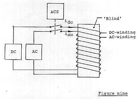
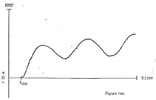
The fuction of the automatic control switch (ACS) is to simultaneously switch on the dc-current, idc and the ac-current, iac at such a time, t = ton, that the instantaneous value of the total magnetomotive force (MMF) is always positive. Thus
Where N1 is the number of turns in the dc-winding and N2 is the number of turns in the ac-winding.Fig. 10 shows the total MMF as a function of time.
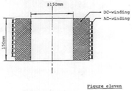
The magnetization coil consists of a dc-winding containing approximately 200 turns of heavy copper wire and an ac-winding containing approximately 10 turns of copper strip wound on top of the dc-winding. Fig. 11 shows a cross section of the coil and its dimensions.
Recommended parameter values :dc-current, idc = 15OA to 180A
ac-current, iac = 0.1 to 0.2A
frequency, f = 1 - 3 MHz.
Stage 8 Inspection
The purpose of this control is to test for the existence of and the correct spacing of the two pole tracks. The measurements can be made with a magnetic flux density meter in combination with a set of control magnets.Stage 9 Assembling
The assembling procedure depends on the application. Used as a mechanical drive unit the magnets must be mounted inside a framework and fitted to a drive shaft. Used as an electric power plant, induction coils must be fitted to the framework.
http://www.borderlands.de/energy.searl.php3?Section=gravity#3
http://www.starwon.com.au/~rayd/searl.htm
http://www.geocities.com/Area51/3066/SEARL.HTM
ANTIGRAVITY:The Dream Made Reality, p26, by John A. Thomas Jr.
(The book "ANTIGRAVITY" is selling in D.I.S.C.Company.)
John A. Thomas Jr.(Q)- Now I was looking at in the old newsletters. It said that in the flying craft only the inner ring was stationary.
John R.R.Searl(A)- No, either that was printed wrong by the chap who wrote it or he misunderstood. All three plates are stationary. They are part of the structure. There are two actions in the generator, no matter what generator it is that you make, whether it's gas, electric or whatever it is. You've got to have one fixed part which can be the field, or the rotor, and a moving magnetic field. Or you can have a stationary magnetic field and you can have a rotary conductor.