Propagated High Frequency Wave Propulsion
 |
What researchers are finding is that some UFOs are sending out an electronic signature of super-high radio-frequency electromagnetic pulses (see the the USAF account of "UFO Encounter One"). The pulses are in the 3 GHz region (the microwave region) of the electromagnetic spectrum at a wavelength of 10 centimeters.
 |
Because the waves are so short and their frequency so high the normal sort of capacitance-inductance oscillator with its conductor / antenna emission systems can't cope and so a different sort of electronics technology is needed to radiate these waves out of the craft and into the air or space around it. There are various methods of doing this with short 'millimeter' waves, one of which is called the transmission line, another is with the parabolic antenna and another is the waveguide. Of these three the best suited system for propagated-electric-field-propulsion is the waveguide, which basically, is a rectangular metal tube whereby at one end the microwave power is pumped in, and at the other end the delivery of those power waves occurs with almost undiminished intensity. The science of waveguides is quite fascinating and is nothing like cable or conductor type electronics, the size and the very shape of a waveguide computes in an entirely different fashion toward the end result. Microwaves though are a very useful range of frequencies; at one particular frequency (3 GHz for atmospheric air) they can then create spin-resonance in the electrons of the atoms of the gases in the surrounding air. Electron spin resonance (ESR) raises the normal-mode 'lower energy' state of the electron up to the higher energy state, the visual effect of which is an emission of light photons of various colours (the subject of which is already covered elsewhere on this website).
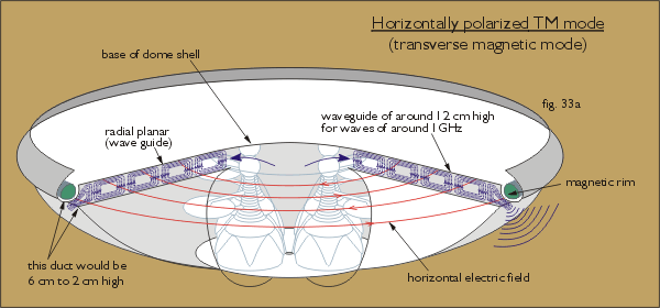
The use of the waveguide is then divided into two propagation modes: transverse electric mode (TE mode) and transverse magnetic mode (TM mode). Strickly speaking the TM mode would produce a horizontal electric field (see fig. 33a below) which is not what is required here, and this sort of wave needs to be completely contained within a tube of four walls and in the present application metallic side-walls would need to be run from the center to the circumferential duct and so it wouldn't be suitable.
 |
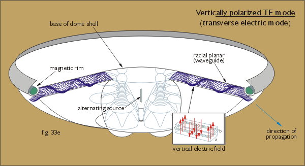
What would be most suitable is the transverse electric mode (TE10), where the magnetic field lines are parallel to the a - b (x - y) plane and the electric field lines are upright and orthagonal (in this case) to the upper and lower planes of the radial planar waveguide (see fig. 33e below). In the TE mode the most important conductor walls are the top and bottom planes because they are the ones that will contain the electric field element of the waves, and in fact microwave propagation can occur through an open-sided parallel-plate waveguide because of this factor (see note 39). The difference being that with open side walls the waveguide will operate through a broader band of wavelengths rather than within one narrow bandwidth which, for the present set of circumstances, is not a disadvantage because the waves will go through a secondary 'shaping' to the required wavelength and frequency when they exit through the circumferential duct.
 |
Directing the Propulsion
If the propagation left the craft's duct through the whole of it's 360º the thrust force would only move the craft straight up (or allow it to come straight down), and so to control the direction of movement the propagation has to be directed by the duct in some way or another. The beauty of a system that utilizes electromagnetic waves in the millimeter range is that those waves can be 'lensed' fairly easily, for just as electromagnetic waves of the light-wave frequency can be focused through glass lenses, so too can millimeter waves be directed through specially constructed 'lenses' made of metal baffles, or with artificial dielectrics (that are formed of a lattice structure), which will change the shape of the wave.
It seems highly likely that Lazar's ufo uses its hull as a form of lens for its wave propagation - see Lazar's Gravity Guide page - so perhaps the Andreasson type does too. At these microwave frequencies the 'optical properties' of the electromagnetic wave can be used to great advantage; and the particularly useful ability of the lens to refract or redirect part of the wave could be used to produce two waves.
Magnetic Trowels
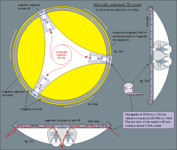
The "magnetic trowel" configurations (shown in these graphics for illustrative purposes as three eye-shaped sectors) (see figs. 33b-d below) work by strobing electric power to magnetic flux producing segments situated inside the circumferential duct, so that they form into three (or two, or four, or however-many) trowels of magnetic flux and rotate around the circumference of the craft and are separated by three (or two, or more) nulls of magnetic flux. This is done by having one segment switched off between the trailing edge of one trowel and the leading edge of the next trowel. The purpose of these trowel configurations is to channel the high frequency electromagnetic waves, that are generated in the center (in the accumulator reactor - see UFO Propagation text) through their waveguide-like forms so as to 'shape' the waves into the required frequency and wavelength - very much in the same way that rectangular metal waveguides are used to shape microwaves. As can be seen in the accompanying diagrams (see figs. 33a) the radial planar waveguide appears to be about 12 cm high, which within a conventional rectangular waveguide would equate to a 625 MHz to 1 GHz frequency wave, but it is quite apparent that at the point where the waves actually exit the craft, at the space between the circumferential rim and the outer edge of the toroid, the height of the duct possibly comes down to between 6 and 2 cm, and this size of waveguide would then relate to a 2 to 4 GHz micro-wave-region frequency (see note 40).
 |
The strobing of the magnetic trowels can be configured to rotate clockwise or counter-clockwise, or they can be made non-rotating. Additionally, the nulls or 'gratings' through which the electromagnetic waves are propagated can be spaced much closer together to within a few wavelengths of each other to facilitate an in-line dual radiation of electromagnetic pulses (as per Mike Competillo's Radio Wave Controlled Electric Field Drive System page). For current research suggests that the most efficient configuration is two power sources (of slightly different frequency), spaced a few wavelengths apart, so that the patterns of constructive and destructive interference work collectively to produce an electric field directional propulsion.
Return to Electrokinetic UFO page